Process Technology: An Introduction - Haan A.B. 2015
16 Development and engineering
16.3 Engineering and construction
16.3.1 Introduction
Once the decision has been made to go ahead with the design and construction of a new plant, the preliminary design resulting from the feasibility study needs to be transformed into detailed plans and specifications for all the components of a chemical plant. The sequence of steps in the design, construction, and start-up of a typical chemical process plant is shown diagrammatically in Fig. 16.5. Three major project phases can be distinguished:
· (1) Conceptual engineering covers the process design, which covers the steps from the initial selection of the process to be used, through to the issuing of the process flow-sheets, and includes the selection, specification, and chemical engineering design of equipment. In a typical organization this phase is the responsibility of the process design group.
· (2) Basic engineering concerns the detailed mechanical design of equipment, the structural, civil and electrical design, and the specification and design of the auxiliary services. These activities will be the responsibility of the specialist design groups. Other specialist groups will be responsible for cost estimation and the purchase and procurement of equipment and materials.
· (3) Detailed engineering, procurement, and construction (EPC) consists of the engineering of the chemical plant, procurement of plant equipment and material, construction, and commissioning. Purchasing agents procure equipment from specialist manufacturers. Construction and installation firms are put under contract to build the plant.
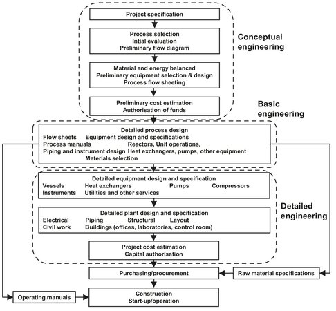
Fig. 16.5: The structure of a chemical engineering project. Adapted from [2].
Chemical plant design and construction projects are complex operations comprising many interrelated activities and personnel from a wide range of disciplines working together in an interdisciplinary setting.
Completion of the project within a predefined time and budget calls for careful organization of the people working on the project, a clear definition of their responsibilities and competences, and an appropriate management concept. A project manager, often a chemical engineer by training, is usually responsible for the coordination of the project, as shown in Fig. 16.6. For the customer the project manager is the first representative of the engineering contractor for the project. In larger projects, project engineers are put under an experienced project manager and take responsibility for the execution of portions of the project. Care should be taken that the final construction and operation of chemical plants are affected by many environmental protection and safety regulations. These requirements have major consequences for plant design and construction. After preliminary discussions with regulatory authorities have begun, it may take two or more years before the application for a construction permit is approved. Because this is a substantial part of the 2—4 years total project duration, the engineering and authority engineering activities must be well coordinated to avoid future delays in the work at the construction site.
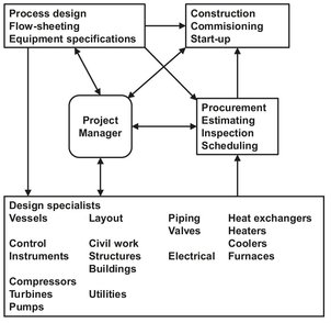
Fig. 16.6: Project organization, Adapted from [2].
16.3.2 Conceptual engineering
Based on the outcome of the feasibility study the decision to proceed to the conceptual design phase can be made. The feasibility study defines the process objective, which provides the basis for process selection. The main task in conceptual design is to obtain a more exact calculation which takes into consideration all costs up until commissioning. The first step toward this objective is to work out the engineering details. Process selection can be done most simply in the form of a block flow diagram (Fig. 16.7), in which each block represents a unit operation or, in complex plants, a plant section containing several unit operations. Lines representing the principal material and energy streams connect the blocks. The first step in process design is to establish the operating parameters for the major stages in the process. The next step is to prepare a process flow diagram from the block flow diagram (Fig. 16.8). Standard symbols are used to represent reactors and other apparatus. The next step is to compile the specifications for all feed stocks, auxiliaries, catalysts, utilities, and products. On the basis of the process flow diagrams, the preliminary process parameters and the specifications are used to prepare material and energy balances for the process steps and finally for the entire process. This objective is achieved through an iterative procedure to modify the process flow diagram and/or the process parameters so that a closed material and energy balance is attained. Process design calculations for multistage interconnected processes with material and energy recycling soon become very complex. Computer tools such as flow sheeting programs (Aspen Plus, Process) enable designers to model unit operations and allow them to be interconnected. A plant can thus be represented as a network of unit operations with material and energy streams in the simulations. The last step in preliminary design is the preparation of a report containing the updated feasibility study, schedules for financing and personnel requirements, a time schedule for the phases of project execution, and a project manual containing all the studies and results from preliminary design.
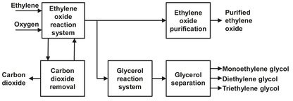
Fig. 16.7: Block diagram of an ethylene oxide and ethylene glycols plant.
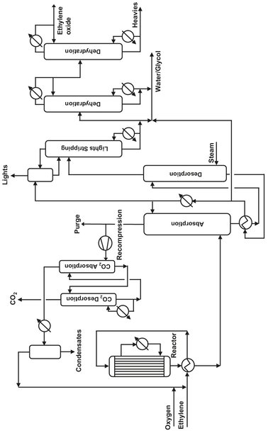
Fig. 16.8: Example of process flow diagram for an ethylene oxide plant.
16.3.3 Basic engineering
Basic engineering is based on the process design which was developed during the conceptual design phase. During basic engineering the geometric dimensions of individual equipment items, the design capacities, temperatures and pressures, construction materials, and the layout of the entire plant are established. These design data are entered in process engineering data sheets which contain all the relevant specifications for the specialist engineer. Material selection should be solved by close collaboration between the materials specialist, the designer, and the process engineer. A process and instrumentation diagram (Fig. 16.9), based on the process flow diagram, is needed for more accurate calculations at the preliminary design stage. For the basic engineering package it should contain dimensions and construction materials for all equipment, machinery and piping as well as the field instruments and control devices required for the operation and control of the plant. The plant layout should not only include approximate data on the position and sizes of the main plant items but also include pipe bridges, roads, control room, compressor buildings etc. The accessibility of plant equipment for repair, maintenance, construction, safety, and inspection must be considered from the very start. If the existing information is adequate the layout should be drawn to scale.
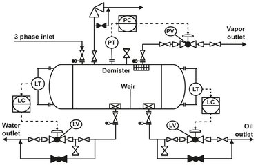
Fig. 16.9: Example of an P & ID diagram.
Once the engineering documents are available, detailed plant costs can be determined. From Fig. 16.10 it can be seen that thanks to a much more detailed knowledge, significant improvement in the accuracy of the estimated investments costs has been achieved compared to when the development phase was completed. The calculation is subdivided into equipment, bulk materials, and indirect costs. Equipment includes all itemized plant equipment such as towers, reactors, heat exchangers, and pumps. The best way to get accurate equipment prices is to submit enquiries to the manufacturers. Such inquiries are time-consuming and accordingly unwelcome. Therefore inquiries are only made with complicated equipment. Simpler items are estimated with in-house documents based on the costs of previously purchased equipment. Bulk materials cover items such as pipes, control systems, electrical equipment, insulation, and paint. Provided the engineering documentation is exact enough, bulk material costs can be calculated fairly accurately by applying unit prices. Other costs include engineering, procurement, construction supervision, commissioning, insurance, price escalation, and contingencies. As opposed to bulk material costs the other costs are calculated for the project as a whole by employing multiplication factors.
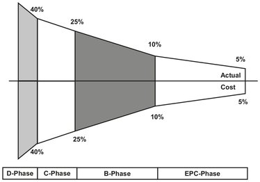
Fig. 16.10: Effect of the project phase on the accuracy of the estimated investment costs.
The final basic engineering documentation includes the process flow diagrams, piping and instrumentation diagrams, plant layout, equipment list, utilities distribution scheme, process engineering data sheets, noise protection concept, electrical equipment list, summary of electrical consumers, data sheets for control equipment and instrumentation, functional process control and instrumentation plan, description of the process control and soil report. The content and level of detail in basic engineering documentation is such that detail engineering can be done without significant difficulties.
16.3.4 Detailed engineering, procurement, and construction
In detailed engineering the engineering and procurement teams prepare detailed plans, drawings, specifications, calculations, and descriptions which needed for bid invitations, selection of manufacturers, vendors and subcontractors, shipping of plant equipment, execution of civil work, erection of plant equipment, and commissioning. Most of the process engineering of a project was performed at the basic engineering stage. In addition, the process engineers devise the plant control concepts, complete piping and instrumentation diagrams, prepare the final process description, and write detailed startup instructions needed for commissioning. The plant layout (plot plan) and piping and instrumentation diagram, created during basic engineering, are continually updated in the course of detailed engineering. The preliminary P & I diagram from the basic engineering is developed and elaborated in detailed engineering. The final P & I diagram describes the whole plant in detail. The P & I diagram contains all essential information developed by the individual disciplines and also includes data provided by the manufacturers of equipment and machinery. Because this information becomes available over a prolonged span of time, the P & I diagram is revised several times in the engineering stage.
All important process engineering data for equipment and machinery have been specified during basic engineering. In detailed engineering the equipment and machinery engineers complete this information. The equipment engineers prepare so-called guide drawings (Fig. 16.11), which are scaled drawings indicating all the dimensions dictated by process engineering. The guide drawings and supplementary information form the technical portion of the bid invitation, which is sent to selected manufacturers. The design office of the manufacturer prepares detailed workshop drawings. Once these drawings have been approved, production can begin. The specification and procurement of machinery are similar to that for apparatus. During piping design all drawings and specifications needed for procurement and installation of the piping components are prepared. The engineering of piping systems is closely linked with the engineering of all other disciplines. Piping accounts for a relatively high proportion of chemical plant costs and piping engineering may represent as much as 20—40% of total engineering. Refineries and petrochemical plants lie at the upper end of this range. Reliable and economic supply of electric power to all consumers is covered during electrical design. Design begins where high-voltage power enters the plant and covers the planning of power generation and distribution, planning of electric utilities, and installation planning. Electrical installation accounts for a 6—10 % of the total chemical plant costs, and so detailed planning is a prerequisite for economic execution.
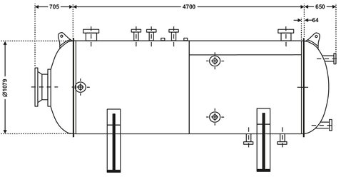
Fig. 16.11: Guide drawing for a vessel.
Procurement activities include the preparation of bid invitations, bid comparisons, purchase of plant components, expediting during the fabrication of plant components, and shipping of plant components to the construction site. The procurement and engineering activities are closely linked together. The main execution phases of a project up to mechanical completion (engineering, procurement, civil work, erection) overlap one another in time. The sequence of engineering work should guarantee that plant equipment with long delivery times is ordered as early as possible, and civil work is begun early so that equipment erection is not delayed. Civil work and erection of a facility are generally subcontracted to specialist firms by the engineering contractor or by the investor. The planning of civil work and erection is part of detail engineering and done by engineers in the civil engineering department assigned to the project team. Often, detailed civil design is assigned to engineering firms in the country where the plant will be built. These firms are familiar with local conditions, know the local regulations, and have short lines of communication to the construction site and the firm performing the civil work. As soon as the engineering work is 25—30 % complete civil work should be started.
Planning the installation of plant equipment starts at a relatively early stage in the engineering process. In large plants, separate schedules are worked out for each plant section. The engineering firm generally directs the construction work performed by specialist subcontractors with the construction manager and his team supervising, coordinating, and directing construction. An overall construction schedule is created during detail engineering. Work at the construction site begins with preparation of the terrain, followed by excavation and foundation work. The first step is the erection of heavy equipment and steel structures. Piping installation at a chemical plant is often the most labor intensive and longest phase of installation. Insulation work starts at vessels, towers, and reactors. Pipes should not be insulated until a given plant section has a sufficiently large number of pipe runs that have been approved for insulation. The installation of electronic devices and control systems takes place after a section of piping has been completed. Devices in control rooms and substations can be installed independent of other work as soon as the buildings have been completed. Functional tests of the installed equipment mark the end of the erection work. These tests are done with the plant in cold condition and with no product.
After mechanical completion of the plant most of the installation personnel leave. Some specialist engineers remain on site to solve problems that arise during commissioning. Commissioning of a plant comprises all the work done after mechanical completion up to certification of the guarantees embodied in the contract. Commissioning must be considered even during basic and detail engineering. Faulty process design can have serious effects on the time required for commissioning and the amount of corrective work needed. The start of production may be significantly delayed, and the owner may suffer a substantial loss of production and revenue. Responsibility for commissioning generally lies with the party granting the process license. Experienced start-up engineers occupy the key positions in the commissioning team. Commissioning takes place according to the steps specified in the operating manual. The first units to be started are utilities and off-sites. During start-up of the plant, initial disorders are almost always encountered. An attempt should be made, however, to get the plant running first and start up all systems, provided the safety of personnel and equipment is not endangered. After operation has stabilized, conditions are optimized. When the planned values of product quantity and quality have been attained the guarantee test is carried out. When the guarantee tests defined in the contract have been passed, the plant is handed over to the owner.